What Jojoba Means?
(həʊˈhəʊbə ) noun. a shrub or small tree of SW North America, Simmondsia californica , that has edible seeds co...
Search over 500,000 articles for practical answers
(həʊˈhəʊbə ) noun. a shrub or small tree of SW North America, Simmondsia californica , that has edible seeds co...
8 8. Empire Axe. 7 7. Tiberius Arms T9. 1 Elite. 6 6. Planet Eclipse Ego 11. 5 5. Planet Eclipse...
These instructions are used to load the 16-bit address into the register pair . We can use this instruction to...
Horses were one of the first things traded in the Columbian exchange. ... Horses allowed Native Americans to trave...
A score of 3 or higher is generally considered good, because that means you passed the exam! A 4 is considered very go...
What best describes the constitution of the United States of America? It is the supreme law of the land . Each...
On a global level, the interest in Linux seems to be the strongest in India, Cuba and Russia , followed by the...
The sodium loses an electron, and the chlorine gains that electron. This reaction is highly favorable because of the e...
Take a much-needed, well-deserved nap. Discover your om: Catch a yoga class. Take a hot bubble bath....
Food such as soil enters the earthworm’s mouth where it is swallowed by the pharynx. Then the soil passes through the...
Perception is the process of selecting, organizing, and interpreting information . This process affects our com...
Economics is a social science concerned with the production, distribution, and consumption of goods and services...
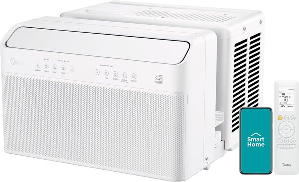
Introducing the 12,000 BTU Inverter Window Air Conditioner with ultra-quiet operation, easy installation, and long-distance airflow up to 20 feet. Perfect for rooms up to 550 sq ft.
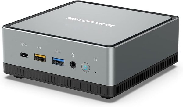
Review of MINISFORUM Mini PC AMD Ryzen 7 3750H UM700: A powerful and compact machine perfect for gaming, business use, and home entertainment.
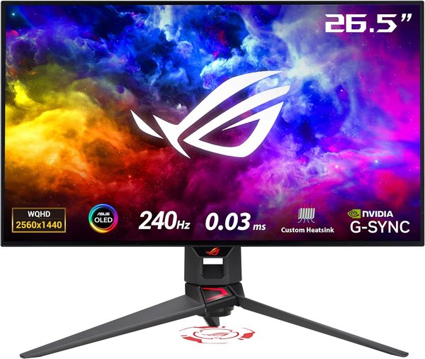
Experience unparalleled gaming performance with the ASUS ROG Swift 27" 1440P OLED DSC Gaming Monitor (PG27AQDM), featuring an OLED panel, 240Hz refresh rate, and G-SYNC compatibility.
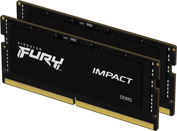
Upgrade your laptop's performance with the Kingston FURY Impact 64GB DDR5 Laptop Memory Kit, featuring fast speeds and energy-efficient design.